Vanishing Point
10 Stage Sequencer with Random Mode
Intro
After the release of The Original Vanishing Point people started requesting things like more stages, lower part count, and the ever elusive random mode so I decided to do another Vanishing Point. Without further hesitation I give you the new and improved Vanishing Point.
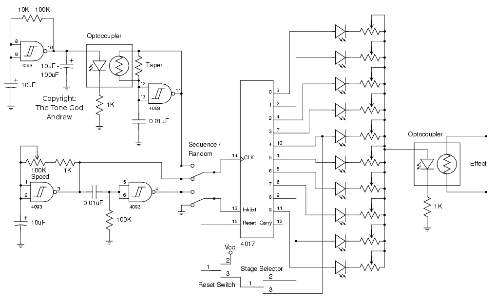
Figure 1
Look Ma, No Audio!
I decided to not include a filter section or any audio for that matter this time around. I also decided that unlike The Original Vanishing Point and other solutions offered on the net not to try to switch the audio signal itself. Instead the audio is interfaced to the control logic through an optocoupler. This will allow people to adapt the Vanishing Point to do whatever they wish. It will also make trouble shooting easier in regards to removing noise since the control logic can be isolated from the audio quite easily.
Control Logic
The heart of the Vanishing Point is the 4017. The 4017 is a 5-bit Johnson decade counter. It has ten decoded outputs that turn on in sequence controlled by a clock pulse. The 4017 does not provide any direction control, ability to have multiple high outputs, or directly select which output is high so it is not possible to have a bounce or pattern mode like The Original Vanishing Point has.
By using the 4017 there is no need to have a counter, decoded the output with a separate IC, then interface that to other circuitry. Its all included in the 4017 which helps reduce the number of logic ICs needed. The only other logic IC used is a 4093 schmitt trigger NAND gate wired as an inverter.
The outputs of the 4017 are tied together through pots. Each pot represents the setting for the particular stage. We can’t just stick pots that are mixed on one end without some type protection stopping the output of each stage from feeding the outputs of all the other stages causing “nastiness”. Something is needed to prevent each output from feeding all the other outputs something like a diode. A simple diode can perform this task but why just stick with a normal diode when we could use a LED ? After all an LED is a Light Emitting Diode. The LED would then indicate which stage is active and the LED’s brightness will indicate what the stage’s setting is. Pretty nifty. With the stages isolated from each other the pots’ output can now feed the LED in the optocoupler.
As each stage is switched high the pot limits the current to both the indicator LED and the LED in the optocoupler that is wired in series which will change the brightness of the LEDs. This result is reflected in the LDR connected to the audio changing value respectively adjusting the parameter connected to the LDR. Simple and clean. No biasing, no signal conditioning, no extra audio wiring.
In the normal sequence mode the 4017 is clocked use a gate from the 4093 (Figure 2). The clock circuit is a pretty simple and common clock for schmitt triggered input gates so I won’t get into its inner workings. As the clock pulses (sequence clock) away the 4017 steps through it’s outputs in sequence. If all we wanted was a sequencer one could ditch the 4093 for a simpler smaller clock source like a signal transistor based oscillator or even a CMOS 555. The circuit would be greatly reduced in size as a result.
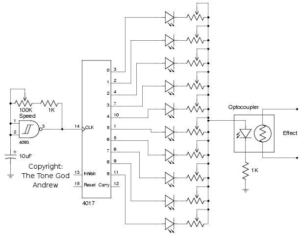
Figure 2
I'm Going Through Stages
If we wanted to limit how many stages the 4017 will cycle through this can be done very simply. The 4017 has a reset pin (pin 15) that when set high forces the 4017 to go back to the first stage. By connecting the output of a stage to the reset pin when the stage output goes high it will cause the sequence to return to the first stage and continue counting from the start again. What number of stages you want the 4017 to be limited to can be set to any value. Note that you tie the reset pin to the stage after you want to set the limit to (i.e. for four stages you connect to stage five, for eight stages you connect to stage 9). When the stage feeding the reset pin goes high it triggers the reset nearly instantly so you won’t notice the reset. After the reset the 4017 will stay at the first stage for the remaining length of the clock cycle the proceed through the sequence again. A switch can be used to select how many stages you want active (Figure 3). In the schematic the ON-OFF-ON switch (stage selector) will select either four, eight, or all ten stages when the switch is open.
If we also wanted the Vanishing Point to stop sequencing when the pedal is off you can connect the reset pin to a pole on a 3PDT bypass footswitch instead of the plain old LED indicator. I think by looking at the pedal and seeing if the LEDs are moving is just as good as an indicator as an LED turning on and off. You can also use the bypass footswitch to stop and re-start the sequence in time. If you wanted to you could hook up the reset pin to a separate footswitch and reset the Vanishing Point on the fly while its on.
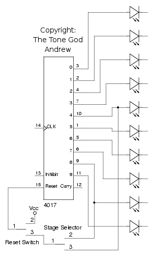
Figure 3
I'm a Random
There has been a fair amount of talk about how to generate random output for sequencers. While at first it may sound easy to make a random result you quickly find out that it is quite hard to generate true random results atleast with discreet components and gates. The best we can do is something that is nearly random, pseudo-random as it were. Through out this article when I say “random” I’m referring to pseudo-random. Other people have thrown out ideas of how to create random output using various bits of logic but I decided to go about it a different way that I think works well and is easy to implement.
Though using the 4017 to reduce the amount of logic was a good idea when it comes to generating random results things can get alittle trickier. The 4017 doesn’t allow for direct control of which stage is active. We can’t arbitrarily select stages so to have the stage selection jump around seemly randomly requires us to go about this differently.
The 4017 will only clock outputs in sequence and in one direction so I thought it would be better to simply cycle through the stages very quickly stopping the 4017 at equal intervals set by the sequence clock. How quickly should the cycling be ? How about fast enough that the eye can’t see it and more importantly faster then the sluggish LDR can respond to. This is accomplished using the same clock circuit as before but tuned much faster. The high frequency clock (HF clock) is connected to the clock input of the 4017.
However there is problem with running two clocks at once for generating random results that being two clocks at once won’t generate random results. When two sources are oscillating the points where two sources are in sync a node, or anti-node depend on the wave form’s state, is formed. These nodes will occur at a regular intervals no matter how fast or slow the clocks go. The frequency of which these nodes occur is called the Beat Frequency (Figure 4). Ever notice when you are tuning your guitar you hear a modulating sound as you get closer and farther from the correct tuning, those are the nodes occurring. The frequency that modulating sounds occurs at is the beat frequency. The same thing happens with our two clocks.
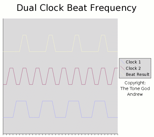
Figure 4
What will happen with a circuit set up like this is after a period of time a sequencing pattern will emerge. This is not necessarily a bad thing. The Original Vanishing Point took advantage of this behaviour for the pattern mode since it allowed for multiple stages to be high but for generating random results this a bad thing. This is why generating random results of any kind from a stable clock source will be difficult. To seem random no reasonably discernible patterns should emerge. We have to do something about the beat frequency.
We can’t prevent the beat frequency phenomena from occurring (that would be playing God!) so in order to reduce the likeliness of a beat frequency inducing a pattern one or both clocks need to have their frequency constantly changing. We want the result to still occur at a regular pace so we can’t change the sequence clock which means we can only play with frequency of the HF clock. Rotating the frequency of the HF clock constantly will make it a “moving target” for the sequence clock to try to create stable a beat frequency. If the HF clock’s frequency is rotated often enough and over a wide range it will make it very tough for a pattern to emerge. Even if the sequence clock hits the right frequency a few times in a row it would need to hit the exact same frequency consistently enough to allow a pattern to emerge. If tuned correctly the likeliness of this happening will be significantly minimized.
There are a few ways to change the frequency of the HF clock. I decided the easiest way would be to use another optocoupler with the LDR replacing the resistor in the RC timing network of the HF clock. The LED in the optocoupler would be driven by another clock (modulating clock) which would cycle at a slower speed (Figure 5). When the clock driving the LED cycles high and low it will change the value of the LDR thus modulate the frequency of the HF clock.
As is the LED being drive by the modulating clock would just flicker on and off thus only providing two different clock frequencies for the HF clock which wouldn’t really help too much since a beat frequency/pattern could still appear. It would be better to have the LED glow on and off causing a gradual and larger spread of change in HF clock’s frequency range. To accomplish this a large capacitor (10uF – 100uF) connected to ground is placed on the output of the modulating clock which will charge and discharge slowly reducing the intensity switching speed of the LED.
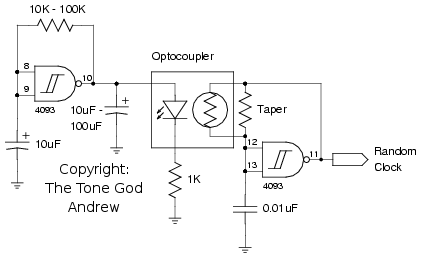
Figure 5
With the LED glowing the frequency of the HF clock is modulated greatly reducing the likeliness of a pattern forming on the output due to a beat frequency (Figure 6). As long as the frequency range of the HF clock is fast enough your eye and the LDR will not notice that the frequency is being modulated.
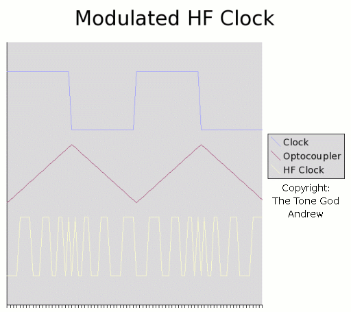
Figure 6
Now that we have a HF clock that is changing frequency feeding the clock input of the 4017 thus cycling through the stages quickly we can focus on stopping the cycling to show the result.
The 4017 provides an enable/inhibit input (pin 13) that when high disables the clock input stopping the 4017. Connecting the same clock used in the sequence mode will cause the 4017 to stop at the same frequency as in the sequence mode. Well sort of. While the enable/inhibit input will stop the clock when high the problem is the sequence clock has a roughly 50% duty cycle meaning its output is high half the time and low the other half. If the clock is connected directly the enable/inhibit input the 4017 will stop for high half the clock cycle and spend the other low half of clock cycle rotating through the stages driven by the HF clock. What we want is a long hold cycle and a very short rotation cycle. To do that the sequence clock’s high pulse have to be extended as to lengthen to hold time and shorten the rotation time.
Using a capacitor and resistor along with another gate we can make what is called a leading edge pulse detector (a.k.a. differentiator) (Figure 7).
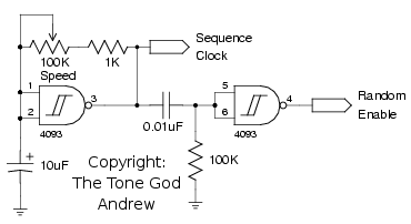
Figure 7
When the sequence clock goes high it charges the capacitor (0.01uF) that is in series on the output. The capacitor is of a small value so it charges up quickly. After the capacitor’s sudden initial charge up a resistor (100K) tied to ground will start to drain it. When the clock goes low it will allow the capacitor to finish discharging. While this behaviour does not help us directly if you take the output of this RC network and feed it into another gate not only do we get an nice clean output but also a shortened pulse. This occurs because the initial charge up of the capacitor goes above the switching threshold of the gate causing the gate to switch low (not high, remember the gate is inverting). When the capacitor starts to drain it passes the gate’s switching threshold causing the gate to go high. The end result is the clock pulse from the sequence clock is shortened thus shortening the rotation cycle and lengthening the hold cycle (Figure 8).
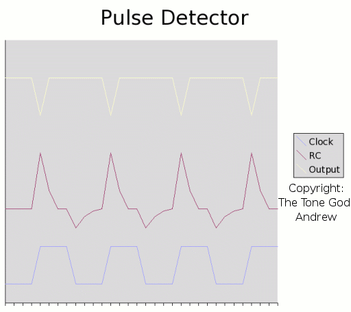
Figure 8
Another added benefit of doing the random mode this way is the stage selector switch will still be effective. We are just rotating through the stages like in sequence mode only very quickly so the stage selector switch will still operate. In random mode the stage selector will prevent the rotation cycle controlled by the HF clock from reaching the other stages thus guarantying that the random result will stay within the stages selected.
Notes
I left some part values off the schematic because it would be hard for me to recommend values in these places. For example the value of the stage pots depends on both the stage LED indicator as well as the LED in the optocoupler. This is something your going to have figure out. Some other values were given a range just as a suggestion.
To get the random mode to work for your tastes you will probably have to tune it a bit. Feel free to play with it.
Clock Noise
Its important to keep the control logic as far as away from the audio as possible. Keep all wires from the control logic tight and away from audio wiring as well. The only wires that should come close to each set of circuits is for the optocoupler.
Connect the ground from the control logic and audio at one point only. Preferable at the battery input. You may also need to isolate the power supplies for the control logic and audio.
High Pitch Whining Shifting
Disconnect the LED in the optocoupler controlling the HF clock from the modulating clock. This should turn off the LED making the LDR go to its highest resistive value which is the slowest setting for the HF clock. Is the whine still there but stopped shifting ? If so the high pitch shifting is the HF being slowed down to the point that its leaking in to the audio.
Use a lower range LDR in the optocoupler. The smaller the value of the LDR the less likely you will get whining. Most LDRs will not go to down to zero ohms so there is little concern that an LDR will be too low. Try to get a LDR with a range in between 100 ohms and 10K. If you can’t find anything in this range you can replace the HF clock’s capacitor (0.01uF) with a smaller value to increase the speed of the HF clock.
You can also attach a pot in parallel to the optocoupler and see if you can dial in a setting that you cannot hear. Measure the pot and install a resistor of that value in its place. A taper resistor position is provided on the board for this function.
Random Not Cycling
If the random is not rotating properly or if it continues to sequence but at a sporadic rate it means the pulse from the pulse detector is too weak or too short for the rotation cycle to occur properly. Increase the 100K resistor on the pulse detector till random results start appearing.
Random cycling occurs too long
How long the random cycling occurs depends on long the low pulse from the pulse detector is. If the cycle is too long reduce the 100K resistor to ground on the input of the pulse detector to shorten the pulse.
Not random enough
If the cycle is short enough to give a good period for cycling but results are still not random enough for your tastes you can increase the resistor in the RC network for the modulating clock driving the optocoupler. Slowing the sweep of the clock means there is a longer sweep of frequencies for the sequence clock to time too decreasing the likeness that your hitting a beat frequency.
Mods
The Vanishing Point is wide open for mods including most of the mods suggested for The Original Vanishing Point so I won’t bother suggesting anymore.
Conclusion
There you have it. That is the Vanishing Point. Hope you like it.
