Lost In State
Controlling Power Up State
Intro
Don’t you just hate it when you turn on those logic controlled pedals (Boss, DOD, Ibanez, etc.) and they start in different on and off states ? Lets see if we can do something about it.
Most logic controlled pedals do not have their initial logic state set at power up. Even if a pedal is consistent on it’s start up state depending on the voltage it is running at it could start up in a different state. This means that the pedal while powered by an adapter starts in one state if you switch to a battery it may start in another state. Even through out the life of the battery as it drains the initial state could change. What we need is something that checks the state on power up and depending on the desired state it will automatically activate the foot switch on the pedal. Cheap, small, simple would nice too. Enter the Lost In State circuit (Figure 1). It is made up of a few different functional bits so lets break it down.
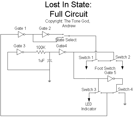
Figure 1
Parts
I’ll be using a 4049 hex inverter for logic (Gates 1-5) and for switching (Switches 1-4) you can use either 4016 or 4066. Since this is logic stuff we are controlling the differences between the two is minimal. I use 4066s because I have alot of them around for things like Wicked Switches.
State Identification Logic
In order to know if we need to activate the foot switch we need to know what the state of the pedal is in. The best way I thought of doing this without messing around too much with the pedal’s circuitry is to tap off the same thing you use to find out what the state the pedal is, the LED indicator. By connecting the switched leg of the LED to an inverter gate (Gate 1) we can drive the rest of the of logic circuit correctly without loading the LED signal. Using another inverter gate (Gate 2) we can can have the option of selecting which state we want the pedal to be in when we power the pedal up (Figure 2) by sending what logic signal we want to the switch (Switch 1).
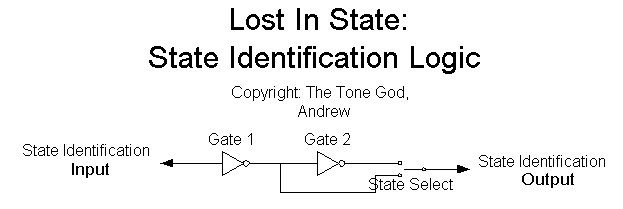
Figure 2
We may think this is all we need to do but this is not the case. All this circuit will do is send out a logic signal to push the switch if the pedal is not in the state we want. It will not release the switch to complete the cycle. We need something else for that.
Timer Logic
If the case comes up that the foot switch is pushed by the state identification logic on power up we need to have some other circuit to release the switch afterwards. A timer that is configured to send out a signal a few moments after power up has occurred can do this job. The easiest way to do this is using a resistor and capacitor that is charged on power up (Figure 3). Setting one of the inverter gates (Gate 3) low at power up will cause the gate to send out a high signal. This high signal will charge the capacitor through the resistor. The capacitor is connected to the input of another gate (Gate 4). Once the capacitor charges up to a certain voltage the gate (Gate 4) will go low. This signal is used control a second switch (Switch 2) that is in series with the switch controlled by the state identification logic (Switch 1) to complete the foot switch operation (Figure 4). By adjusting the resistor and capacitor you can control how long it takes for the gate (Gate 4) to go low.
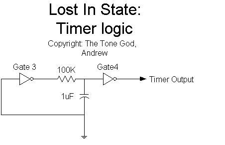
Figure 3
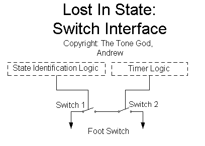
Figure 44
Note:
Sometimes there is a little power up pulse in the Lost In State circuit that MAY trigger the foot switch. As long as you make the length of the timer long enough the circuit will take care of this pulse.
Disconnect Circuit
So now we can check the state on power up, activate the switch if needed to, and then release the switch. We’re done right ? Well not yet. The circuit will interfere with the operation of the pedal after the power up. We need to disconnect the Lost In State circuit from the rest of the pedal after the power up. This is not to tough to do since we have access to a timer that sends a signal out when the Lost In State circuit is finished. Using the timer signal to control some spare switches (Switches 3 and 4) the Lost In State circuit can removed itself from the rest of the pedal circuit (Figure 5). The state identification circuit is connected to the LED indicator through a switch (Switch 3). When the timer sends out the low signal it opens a switch (Switch 3) disconnecting the state identification logic from the LED indicator. A gate is used to invert the signal coming from the timer logic (Gate 5) sending a high signal to another switch (Switch 4) closing it which ensures proper clean up of the state identification logic. The switch that is in series with the foot switch is already open at this time (Switch 2) so the Lost In State circuit has now removed itself from the pedal allowing for proper operation of the pedal.
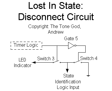
Figure 5
Sequence of Events
Now that all the sections of the Lost In State circuit has been explained lets go through the sequence of events that occur when the pedal is powered up with the Lost In State circuit attached.
1. Power turned on
2. Gate 3 sends out a high signal which starts to charge the capacitor through the resistor.
3. While the capacitor is charging Gate 4 is sending out a high signal causing Switch 2 to be closed.
4. After the pedal’s logic has initialized the LED output is used as input to Gate 1.
5. Depending on which gate, Gate 1 or 2, is selected Switch 1 will be set accordenly. If the the state of the pedal is in the incorrect state Switch 1 is closed. If the the state of the pedal is in the correct state Switch 1 is opened.
6. While Switch 2 is closed if Switch 1 is closed then the foot switch is activated. If Switch 1 is open then the foot switch is not activated.
7. The capacitor has charged to point of causing Gate 4 to send out a low signal. This causes Switch 2 to open.
8. If Switch 1 was closed then when Switch 2 opens this completes the foot switch operation. If Switch 1 was open then nothing happens.
9. With Switch 2 open the Lost In State circuit is disconnected from the pedal’s foot switch.
10. Switch 3 is opened disconnecting the Lost In State circuit from the pedal’s LED indicator.
11. Gate 5 closes Switch 4 thus setting the LED indicator input of the Lost In State circuit.
12. Pedal operates as normal.
Thats all folks.
