Opamp-eration
Converting Opamps to work in Signal or Split Supplies
Intro
Occasionally you will run into a schematic that contains opamps but runs on a split power supply. Don’t give up. With a little know how and a few parts most opamp based circuits can be converted to run off single supplies. Let get to it.
Split and Single Supplies
Just so its understood what is being said here is a quick definition. A single supply has one polarity when referenced to ground. Its really a single polarity supply but is called single supply. Usually in a single supply you have positive and ground.
Split supplies (a.k.a. dual supply, bi-polar, etc.) have both polarities when referenced to ground, positive and negative.
But It Says _______ Supply
Lets get this out of the way first. You may see schematics or datasheets that speak of split or single supply opamps. The truth of the matter is almost all opamps can run in either split or single supply circuits.
One of the nice things about opamps is they don’t have a ground reference pin. What that means the opamp does not know what its reference is to the power supply. It doesn’t know if the power supply is +9v and -9v, or +18 and ground, or +6 and -13, or whatever.
Why Did It Dang Broken My Opamp ?
So if an opamp doesn’t care what its power supply is why does an opamp stop working when you switch it from a dual supply to single ? While the opamp does not have a reference to ground chances are your audio signal does. In most audio situations the audio signal is reference to ground like say through your cable/jack. This make a difference because now that something is reference to ground the power supply polarity comes into play. Here is why.
With our signal, which is AC, referenced to ground the signal swings above (positive) and below (negative) the ground reference. With an opamp running in split supply this is fine since the power supply provides both polarities (Figure 1). If we just change the power to single supply (Figure 2) when the signal swings below ground going negative the opamp amp can’t do it since the power supply doesn’t supply negative thus the opamp stops working.
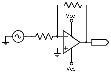
Figure 1
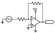
Figure 2
I said the power supply does not matter and that opamps can run in a single supply, what gives ? Both statements are still true. The power supply is not really the issue here. What is at issue is the reference point of the signal. If we move the signal or its reference point to somewhere in the power supply range then the opamp will work again (Figure 3).
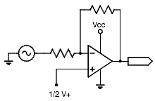
Figure 3
Making a New Start
Be it bias point, reference voltage (usually labeled as Vr), virtual ground, or whatever you want to call it its about creating a new reference for the opamp. This is a very easy thing to do. A pair of resistors is all that is needed. Usually the resistors are of equal value to provide a voltage that is half way between the power supply thus giving an equal range of swing above and below the reference point (Figure 4).
What size resistors you should use depends on what your doing. With high speed stuff you can use 1-1K ohms but they consume more power. 1M-10M ohms use less power which may sound like a good idea but allow for more noise. Usually 1K-100K ohms, or even up to 1M if you want, is good for general purposes. A capacitor is connected from the new reference point to ground to provide noise filtering for the reference point.
In most cases the two resistor/one capacitor solution is sufficient but if you need to deal with possible load issues you can use another opamp to make an active bias point. Take your passive bias point (Figure 4) and connect it to an opamp setup as a buffer (Figure 5).
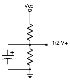
Figure 4
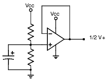
Figure 5
Let The Conversions Begin
Now for the fun part. Armed with a little new knowledge and a solid reference point the conversion can begin. The basic concept to converting an opamp circuit is generally the same but applied differently depending on what mode the opamp is running in that being non-inverting or inverting mode. Lets tackle the inverting opamp circuit first.
In an inverting opamp circuit the reference point of the circuit is set at the non-inverting input (+). In split supply circuits this is normally set to ground (Figure 6). To have the opamp circuit operate in single supply the non-inverting input should be set to the reference point we have created (Figure 7). With the new reference point set the opamp should operate normally.
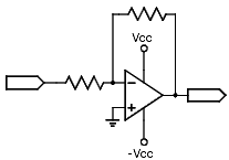
Figure 6
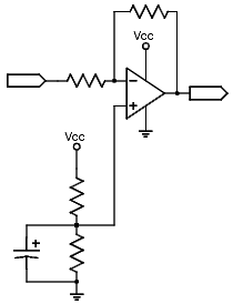
Figure 7
Non-inverting opamp circuits are a little tougher to convert because there is no isolated reference point that can be quickly set like with the inverting circuit (Figure 8). Instead the input signal has to be bias into the new reference point so the signal itself swings in the reference range.
To rebias the input signal you have to first make sure you are DC decoupling the input signal by using a capacitor if there is not one already in the circuit. This will block any incoming DC that could throw off your biasing. With the decoupling taken care of you can bias the signal by attaching your reference point after the capacitor (Figure 9). This will bias the incoming signal to a voltage that will swing within the power supply.
Notice that there is no filtering capacitor in this bias network. It may be needed but most of the time you can get away without it. If you do need it some of your orignal signal will be filtered as well.
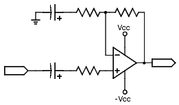
Figure 8
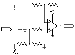
Figure 9
Wanna Share...The Reference Point ?
You may not need a separate reference point for every opamp in the circuit. Sometimes multiple opamps can use the same reference point. For example with inverting opamp circuits since the reference voltage is set at an isolated point another opamp can share that same reference point (Figure 10).
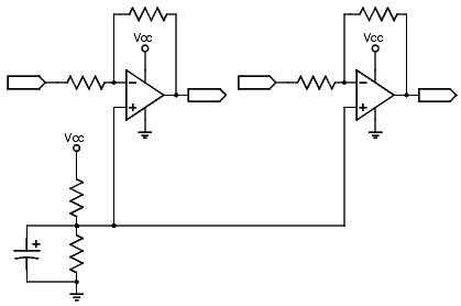
Figure 10
Non-inverting circuits have other issues though. Biasing is done by adjusting the input signal. While connecting bias point together might seem like a good idea you are connecting inputs together too (Figure 11). That is BAD. This is a case where you need separate reference points for each input.
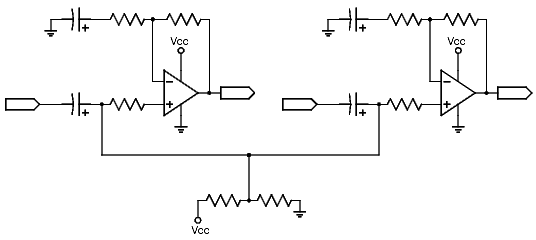
Figure 11
There may be other cases where you may need separate reference points for each opamp. Loading, noise, current limitations, etc. can make using shared reference points a problem. In some cases you may be able to use the active bias point (Figure 12) to overcome these problems. Testing is always recommended before you decide to share reference points.
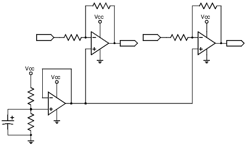
Figure 12
Possible Problems
These power supply conversion techniques are centered around opamp based circuits. If the circuit has other ICs or discreet parts who’s defined behavor is voltage dependent they may take issue with the power supply being changed. Components may have their biasing off set by the power supply change. Components may need the extra voltage provided by the split supply. Components may not even work without a split supply. Some of these situations can be delt with by tweaking components or doing some kind of voltage doubler/inverter but that is beyond the scope of this article.
Final Words
Most of these circuits will now work with single supplies. In fact in most situations they will work in either single or split supply situations without the need for change since the circuits now use their own reference points that are not depended on the definition of ground.
If you really wish to convert opamp circuits from single supply to split supply for lower part count and/or simplicity sake just um…read the article backwards ignoring any backward messages except those involving beer.
Now…reeb a em teg.
