Follow Debouncing Ball
Switch Debouncing
Intro
Stomp switches are great things but there is a hidden dark side to those beloved switches especially when it comes to using them for logic control. That dark side is switch bounce. When a mechanical switch operates it does not make a clean connection. Tension, vibration, dirt, oil, corrosion, age, and other factors cause the switch’s contacts to bounce against each other making and breaking contact before settling in its new state (Graph 1). This can cause havoc especially for circuits that want to see clean switching like digital logic circuits.
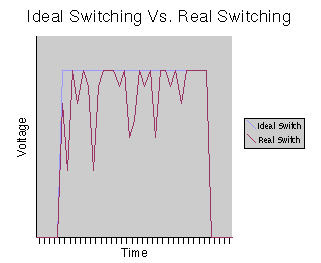
Graph 1
Commonly there are two types of input that a switch is used for in digital logic.
Data Input
This is when the state from the switch is being used for data. An example is the toggle versions of the Wicked Switches. The state information from the switch is being used as the control data for the switching IC. Switch bounce is not a horribly bad thing here but if the switch bounces badly then the dirty data it is sending out could cause a false trigger of the switching IC(s) resulting in popping. Not fun stuff.
Clock Input
This is when the state from the switch is being used as timing event to trigger some IC(s) to send out different data. An example is the momentary Wicked Switches where the switch is being used to trigger the flip-flop. Here dirty switching information can be worse. If improper debouncing is employed then the dirty input could cause an unwanted state change and since you can’t predict how much switch bounce there will be you are really gambling as to what state you’ll end up with when you operate the switch. Even less fun stuff.
Now lets look at the various ways switch bounce can be combatted.
Switch Debouncing Solutions
Some of the following solutions are designed to give a specific type of output so some solutions may not work depending on what you are trying to do.
Mechanical
Switch technology has improved greatly over time resulting in the switch bounce situation to be almost non-existent, unless you still want to use large mechanical switches which musicians still love, myself included.
Computer keyboard style switches have a mechanism that either guide a set of contacts together or separates them thus blocking the contacts from bouncing against each other. Tactile switches that provide a snap connection resulting in a clean pulse are available. Listen to the click from your mouse button. Membrane switches are another improvement that have come along. These are found being used for things like keyboards on watches, remotes, calculators, etc. Its a sheet of rubber with a tip of rubberized conductive material that when pressed makes a connection with a set of exposed contacts on the circuit board. The rubber is soft therefore provides a soft connection that has little to no bounce. Also they help seal the contacts from getting dirty and since its not a high stress mechanical operation it will last longer. The main problem is that most of these solutions don’t stand up very well to the high impact stress of being stepped on. We want big switches so these solutions are generally not for the DIYer.
Resistor/Capacitor Network
Probably the most common and easiest method of debouncing used. It is simply a resistor and capacitor wired together with the switch connected to the central connection (Figure 1). The capacitor is charged through the resistor so the default state when the switch is not engaged is high which you will see in the graphs using the R/C network. When the switch is engaged it slowly drains the capacitor to ground thus softening any small bounces (Graph 2). It works well enough moderating some bounce but it doesn’t eliminate it completely. In order to eliminate it completely you would have to use a very slow discharging R/C ratio which would end up being too slow in response of the momentary switch operation to provide accurate information. Sometimes in a batch of switches you will get some really bouncy switches that this system may not fully cure. You can try to adjust the R/C ratio but that can be annoying to do for every switch. Lastly the state information coming from the switch is not really digital so to control something like a switching IC with this won’t work very well.
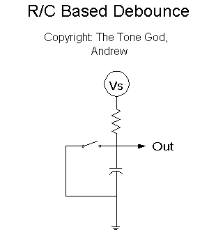
Figure 1
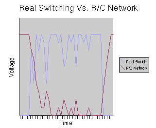
Graph 2
Resistor/Capacitor Network with Digital Logic
In order to use the switch state information properly we need to do some basic analog-to-digital conversion. This comprises of a logic gate tacked on to the R/C network which we are still using to soften the mild bumps but in the switch information (Figure 3). The logic gate has a certain voltage threshold at which it changes its output state. This provides some more tolerance to switch bounce but switch bounce can still leak through (Graph 3).
We can add some more bounce tolerance by using logic gates with Schmitt triggers. Schmitt triggered gates have two different threshold levels at which they change state instead of the just the one with normal logic gates. With a Schmitt trigger when the voltage drops below the first threshold it will not switch state again, even if the voltage cross the same threshold, until the other higher threshold is reached. This will reduce the sensitivity the Schmitt triggered gate has for switch bounce (Graph 4).
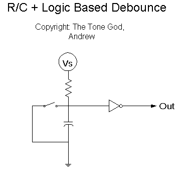
Figure 3
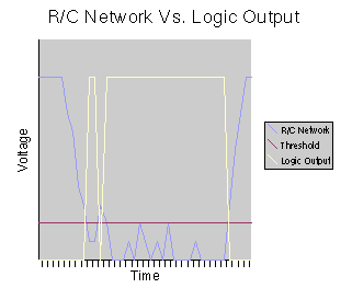
Graph 3
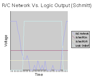
Graph 4
Digital Latch
By using two logic gates together we can create a latch circuit. One gate is always driving the other gate’s input high so in order to change the output state we need to bring one of the gate’s input past it’s switching threshold. When this happens the gate’s new state is reinforced by other gate. The two gates switching thresholds create a pair of switching thresholds for the latch similar to the idea of the Schmitt trigger’s separate switching thresholds but instead of having one gate with two different thresholds we use two gates and their thresholds. The thresholds are going to be much closer to the high and low state voltages then the Schmitt trigger’s thresholds so any switch bounce that occurs between the thresholds will be ignored. You need a switch so bouncy that the voltage jumps between the thresholds in order for the output state to change.
Making a latch is not that hard to do as it can done many ways (Figure 4, 5, 6) but sometimes it does require a few extra parts.
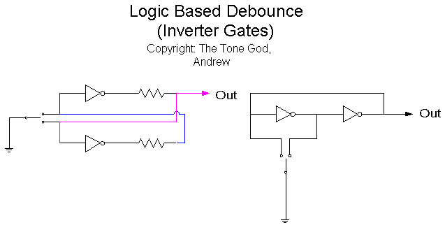
Figure 4
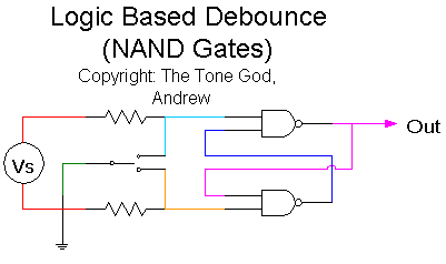
Figure 5
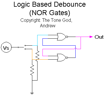
Figure 6
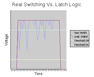
Graph 5
Opamp/Comparator
If you don’t have any digital logic devices lying around we can use other devices like opamps. Opamps are capable of being used as logic devices with particularly interesting properties that we can take advantage of for debouncing. When opamps are used as comparators the output will only go high when both input’s voltages are very close to each other. (Just how close the voltages have to be depends on which opamp you use. Consult your local datasheet.) We can use one input to set a switch threshold of own choosing (Figure 7).
Our initial thought may be to set the threshold to the voltage that switch will output when operated but with the opamp being so sensitive to voltage differences the bounce that occurs at the height of the switching cycle will come out (Graph 6). We can add an R/C network for extra bounce resistance (Figure 8) but while some of the noise is reduced there is still some bounce getting through (Graph 7).
Instead if we set the threshold at the voltage where the switch sits when not operated the resulting output will be much cleaner (Graph 8). Sticking an R/C network on won’t do much now (Graph 9) unless you have a REALLY noise switch in which case you can put one on.
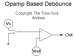
Figure 7
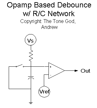
Figure 8
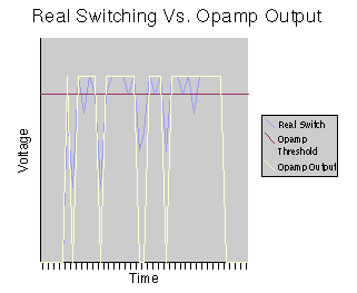
Graph 6
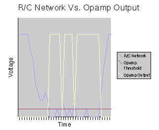
Graph 7
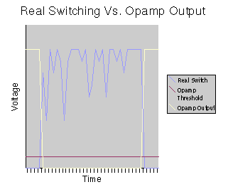
Graph 8
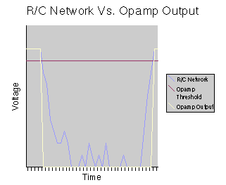
Graph 9
If you have a couple more opamps lying around (say if you use a quad opamp package) you can build a flip-flop using the resulting output from the debouncing opamp as the clock pulse. I thought I would throw that one in for free (Figure 8).
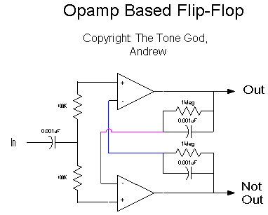
Figure 8
Triggered Timers
A clean clock pulse can be created by using a timer IC configured as a triggered one-shot pulse generator. This is a signal generator that will send out one pulse cycle for a specified period of time when the input is triggered. For the duration of the pulse cycle the trigger input will be ignored even if it is activated again either by switch bounce or manual switch operation. By setting the length of the pulse to be longer then the time it takes the switch to complete its state change when operated we will get a very clean clock pulse.
Using the ever popular and available 555 timer we can generate a clock pulse that is about 0.1 milliseconds long (Figure 9) which should be enough time for the switch to settle into its new position resulting in a nice clean pulse (Graph 10).
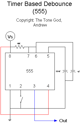
Figure 9
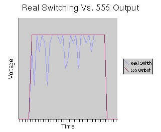
Graph 10
Special ICs
There are specialized ICs for interfacing mechanical switches to digital logic but they are expensive, hard to get, sometimes hard to use, and use up good board space. As you can see we can get excellent results using regular and easily available parts.
I hope that the topic of switch debouncing has been made a tad clearer for you.
